B2B , B2C , C2C

0

Business-to-business (B2B) describes commerce transactions between businesses, such as between a manufacturer and a wholesaler, or between a wholesaler and a retailer. Contrasting terms are business-to-consumer (B2C) and business-to-government (B2G).

The volume of B2B transactions is much higher than the volume of B2C transactions. The primary reason for this is that in a typical supply chain there will be many B2B transactions involving subcomponent or raw materials, and only one B2C transaction, specifically sale of the finished product to the end customer. For example, an automobile manufacturer makes several B2B transactions such as buying tires, glass for windshields, and rubber hoses for its vehicles. The final transaction, a finished vehicle sold to the consumer, is a single (B2C) transaction.


Business-to-consumer (B2C, sometimes also called Business-to-Customer)describes activities of businesses serving end consumers with products and/or services.

An example of a B2C transaction would be a person buying a pair of shoes from a retailer. The transactions that led to the shoes being available for purchase, that is the purchase of the leather, laces, rubber, etc. as well as the sale of the shoe from the shoemaker to the retailer would be considered (B2B) transactions.


Consumer-to-consumer (C2C) (or citizen-to-citizen) electronic commerce involves the electronically-facilitated transactions between consumers through some third party. A common example is the online auction, in which a consumer posts an item for sale and other consumers bid to purchase it; the third party generally charges a flat fee or commission. The sites are only intermediaries, just there to match consumers. They do not have to check quality of the products being offered.

Examples of C2C

This type of e-commerce is expected to increase in the future because it cuts out the costs of using another company. An example on cited in Management Information Systems, is for someone having a garage sale to promote their sale via advertising transmitted to the GPS units of cars in the area. This would potentially reach a larger audience than just posting signs around the neighborhood.


HOmesick!!!

0

hOmesick.homesick.
nape la aku ni asek2 homesick..
aku rindu umah..rindu org2 kt umah..rindu kucing2 aku.
gile rindu!!
ahh..xpe2..
sabO..da nk cuti SEM..
tp......
EXaM mENaNti aku la doe..
excited ke nervous??
tahlaa..no KOmen..
huhuu..
bengong aku ni..

yg penting.
lamBAT sgt mase berlaLu laa
;(

UTP and STP

0


Twisted pair cabling is a form of wiring in which two conductors (the forward and return conductors of a single circuit) are twisted together for the purposes of canceling out electromagnetic interference (EMI) from external sources; for instance, electromagnetic radiation from Unshielded Twisted Pair (UTP) cables, and crosstalk between neighboring pairs.


Unshielded twisted pair (UTP)


Unshielded twisted pair

Twisted pair cables were first used in telephone systems by Alexander Graham Bell in 1881. By 1900, the entire American telephone line network was either twisted pair or open wire with similar arrangements to guard against interference. Today, most of the millions of kilometres of twisted pairs in the world are outdoor landlines, owned by telephone companies, used for voice service, and only handled or even seen by telephone workers.

UTP cables are found in many ethernet networks and telephone systems. For indoor telephone applications, UTP is often grouped into sets of 25 pairs according to a standard 25-pair color code originally developed by AT&T. A typical subset of these colors (white/blue, blue/white, white/orange, orange/white) shows up in most UTP cables.

For urban outdoor telephone cables containing hundreds or thousands of pairs, the cable is divided into smaller but identical bundles. Each bundle consists of twisted pairs that have different twist rates. The bundles are in turn twisted together to make up the cable. Pairs having the same twist rate within the cable can still experience some degree of crosstalk. Wire pairs are selected carefully to minimize crosstalk within a large cable.


Unshielded twisted pair cable with different twist rates

UTP cable is also the most common cable used in computer networking. Ethernet, the most common data networking standard, utilizes UTP cables. Twisted pair cabling is often used in data networks for short and medium length connections because of its relatively lower costs compared to optical fiber and coaxial cable.

UTP is also finding increasing use in video applications, primarily in security cameras. Many middle to high-end cameras include a UTP output with setscrew terminals. This is made possible by the fact that UTP cable bandwidth has improved to match the baseband of television signals. While the video recorder most likely still has unbalanced BNC connectors for standard coaxial cable, a balun is used to convert from 100-ohm balanced UTP to 75-ohm unbalanced. A balun can also be used at the camera end for ones without a UTP output. Only one pair is necessary for each video signal.


Cable shielding


S/UTP cable format

S/UTP, also known as FTP
S/STP, also known as S/FTP.

STP cable format

S/STP cable format


Twisted pair cables are often shielded in attempt to prevent electromagnetic interference. Because the shielding is made of metal, it may also serve as a ground. However, usually a shielded or a screened twisted pair cable has a special grounding wire added called a drain wire. This shielding can be applied to individual pairs, or to the collection of pairs. When shielding is applied to the collection of pairs, this is referred to as screening. The shielding must be grounded for the shielding to work.

Screened unshielded twisted pair (S/UTP)
Also known as Fully shielded[citation needed] (or Foiled) Twisted Pair (FTP), is a screened UTP cable (ScTP).
Shielded twisted pair (STP or STP-A)
STP cabling includes metal shielding over each individual pair of copper wires. This type of shielding protects cable from external EMI (electromagnetic interferences). e.g. the 150 ohm shielded twisted pair cables defined by the IBM Cabling System specifications and used with token ring networks.
Screened shielded twisted pair (S/STP or S/FTP)
S/STP cabling, also known as Screened Fully shielded Twisted Pair (S/FTP), [1] is both individually shielded (like STP cabling) and also has an outer metal shielding covering the entire group of shielded copper pairs (like S/UTP). This type of cabling offers the best protection from interference from external sources, and also eliminates alien crosstalk[1].


Note that different vendors and authors use different terminology (i.e. STP has been used to denote both STP-A, S/STP, and S/UTP).


Advantages

  • It is a thin, flexible cable that is easy to string between walls.
  • Because UTP is small, it does not quickly fill up wiring ducts.
  • UTP costs less per meter/foot than any other type of LAN cable.


Disadvantages

  • Twisted pair’s susceptibility to the electromagnetic interference greatly depends on the pair twisting schemes (usually patented by the manufacturers) staying intact during the installation. As a result, twisted pair cables usually have stringent requirements for maximum pulling tension as well as minimum bend radius. This relative fragility of twisted pair cables makes the installation practices an important part of ensuring the cable’s performance.
  • In video applications that send information across multiple parallel signal wires, twisted pair cabling can introduce signaling delays known as skew which results in subtle color defects and ghosting due to the image components not aligning correctly when recombined in the display device. The skew occurs because twisted pairs within the same cable often use a different number of twists per meter so as to prevent common-mode crosstalk between pairs with identical numbers of twists. The skew can be compensated by varying the length of pairs in the termination box, so as to introduce delay lines that take up the slack between shorter and longer pairs, though the precise lengths required are difficult to calculate and vary depending on the overall cable length.

RCA JACK

0

Definition: An RCA Jack or RCA Plug is a connector commonly used to connect various components in a audio-video system. It is used for analog and coaxial digital audio and composite and component video connections.
Also Known As: phono connector


Uses

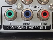
RCA jacks, here used for YPbPr video output.

In the most normal usage, cables have a standard plug on each end, consisting of a central male connector, surrounded by a ring. The ring is often segmented for flexibility. Devices mount the jack, consisting of a central hole with a ring of metal around it. The ring is slightly smaller in diameter and longer than the ring on the plug, allowing the plug's ring to fit tightly over it. The jack has a small area between the outer and inner rings which is filled with an insulator, typically plastic (very early versions, or those made for use as RF connectors used ceramic).

As with many other connectors, the RCA has been adopted for other uses than originally intended, including as a power connector, an RF connector, and as a connector for loudspeaker cables. Its use as a connector for composite video signals is extremely common, but provides poor impedance matching. RCA connectors and cable are also commonly used to carry S/PDIF-formatted digital audio, with plugs colored orange to differentiate them from other typical connections.

Connections are made by pushing the cable's plug into the female jack on the device. The signal-carrying pin protrudes from the plug, and often comes into contact with the socket before the grounded rings meet, resulting in loud hum or buzz if the audio components are powered while making connections. Continuous noise can occur if the plug partially falls out of the jack, breaking ground connection but not the signal. Some variants of the plug, especially cheaper versions, also give very poor grip and contact between the ground sheaths due to their lack of flexibility.

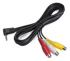
They are often color-coded, yellow for composite video, red for the right channel, and white or black for the left channel of stereo audio. This trio (or pair) of jacks can be found on the back of almost all audio and video equipment. At least one set is usually found on the front panel of modern TV sets, to facilitate connection of camcorders (through 3.5mm Jack to 3 RCA, also called Mini RCA plug), digital cameras, and video gaming consoles. Although nearly all audio-visual connectors, including audio, composite and component video, and S/PDIF audio can use identical 75 Ω cables, sales of special-purpose cables for each use have proliferated. Varying cable quality means that a cheap line-level audio cable might not successfully transfer component video or digital audio signals due to impedance mismatch and poor shielding quality (causing signal-to-noise ratio to be too low). Cables should meet the S/PDIF specification as defined by the international standard IEC 60958-3 for assured performance.

The male plug has a center pin which is 3.70 mm in diameter, and is surrounded by an outer shell which is 8.25 mm in diameter.


Disadvantages

"Bullet plug" variation. Notice the hollow center conductor and the single pin point for the return signal.

One problem with the RCA jack system is that each signal requires its own plug. Even the simple case of attaching a cassette deck may need four of them, two for stereo input, two for stereo output. In any common setup this quickly leads to a mess of cables, which is made worse if one considers more complex signals like component video (a total of three for video and two for analog audio or one for digital coaxial audio).

There have been numerous attempts to introduce combined audio/video connectors for direct signals[citation needed]but in the analog realm none of these have ever become universal, except in Europe where the SCART connector is very successful[citation needed]. For a time the 5-pin DIN connector was popular for bi-directional stereo connection between A/V equipment, but it has been entirely displaced[citation needed] on modern consumer devices. Though RF modulators inherently transmit combined A/V signals in video applications, they depend on broadcast television systems and RF connectors which are not universal worldwide; RF signals are also generally inferior to direct signals due to protocol conversion and the RF limitations of the three major analog TV systems (NTSC, PAL and SECAM).

Nearly all modern TV sets, VCRs, and DVD players sold in Europe have SCART connectors[citation needed], though sometimes supplemented by RCA and/or RF connectors and there are also SCART-RCA adapters.[1] Outside Europe, separate RCA connectors are the norm[citation needed], supplemented by RF connectors for backward compatibility and simplicity; though mini-DIN connectors are sometimes used for S-Video connections, composite video, component video, and analog audio (mono or stereo) all use RCA connectors unless RF is used. In the digital realm, however, combined A/V connectors are gaining ground; HDMI is commonly being used today, and DisplayPort is a potential competitor to HDMI.

For audio signals, an RCA connection is called unbalanced, and a true balanced connection is generally preferred in certain applications because it allows for the use of long cables while reducing susceptibility to external noise.